Preface
I've spent a fair amount of time talking to workshop technicians over the past couple of years, and one thing that keeps coming up is this feeling of professional vertigo — the sense that the ground has shifted beneath their feet without much warning. A mechanic who spent twenty years confidently diagnosing internal combustion engines now finds himself staring at a 400-volt battery pack wondering which probe to reach for first. It's not that the fundamentals of electrical measurement have changed. It's that the consequences of getting them wrong have grown dramatically, and the types of signals that need to be analyzed have expanded far beyond what a standard multimeter was ever designed to handle.
This article is an attempt to map the terrain. It covers what new energy vehicle (NEV) maintenance actually demands from test instruments, where conventional tools come up short, and how purpose-oriented instruments — particularly oscilloscopes with integrated multimeter capability — fill the gaps that are widening as the global EV fleet keeps growing. We will also look specifically at how BSIDE's product line addresses these requirements, not as a sales pitch, but as a technical walkthrough of why the specs on these instruments were designed the way they were.
1. The Electrification Wave and Its Aftermarket Consequences
The scale of the shift underway in automotive transportation is genuinely difficult to overstate. Global sales of electric passenger cars surpassed 17 million units in 2024, capturing more than one in five new cars sold worldwide. In China — by far the most active market — roughly one in two new vehicles sold carries an electric drivetrain. The global EV fleet now stands at approximately 58 million vehicles, and every projection points steeply upward: the IEA anticipates more than 20 million electric cars sold in 2025 alone, pushing the share of new sales beyond one in four globally.
These numbers have a direct and underappreciated consequence for aftermarket service. A car sold today will be in someone's workshop within a few years, either for routine maintenance or fault diagnosis. The workshop that successfully handles these vehicles is not simply the one with access to the right OBD adapter. It is the one whose technicians understand the unique electrical architecture of battery electric vehicles, whose safety protocols are genuinely calibrated to the hazards present, and — critically — whose bench instruments are capable of capturing the signals that actually tell the story of what is happening inside these vehicles.
What the industry is only beginning to grapple with is that a significant proportion of currently certified automotive technicians have limited training with high-voltage systems. Research from the Institute of the Motor Industry in the United Kingdom found that only around five percent of active technicians hold qualifications to work on electric vehicles. The skills gap is real, and instrument accessibility is a meaningful part of closing it. Tools that combine multiple measurement capabilities, that handle both AC and DC high-voltage environments, and that present complex waveforms in readable formats can meaningfully shorten the learning curve for technicians transitioning from ICE to NEV work.
2. Why NEV Diagnostics Is Fundamentally Different
To understand what instruments NEV maintenance demands, it helps to understand what makes the electrical architecture of a battery electric vehicle different from what most automotive technicians spent their careers working on.
A conventional gasoline vehicle runs a 12-volt chassis-grounded electrical system. The negative terminal of the battery is bonded to the vehicle chassis, which serves as the return path for virtually all the vehicle's circuits. The complexity is real — modern ICE vehicles carry hundreds of ECUs and kilometers of wiring — but the fundamental logic of the electrical system has not changed much in decades. Voltage is low enough that direct contact, while unpleasant, is rarely fatal. Measurement is relatively forgiving.
A battery electric vehicle floats its high-voltage system electrically above chassis ground. This is not an oversight — it is a deliberate safety architecture. The HV battery pack, which typically operates somewhere between 300 and 800 volts depending on the platform, maintains no intentional connection to the vehicle's metal structure. The motor drive inverter, the DC-DC converter, the on-board charger, and the EV air conditioning compressor are all part of this isolated high-voltage island. A separate Insulation Monitoring Device (IMD) runs continuously while the vehicle is on, measuring the resistance between this floating HV network and the chassis. If it detects that insulation has degraded — perhaps because a coolant leak has bridged the gap, or a cable has chafed against a structural member — it raises a fault and can disable the drivetrain before a lethal leakage path develops.
This architecture creates a set of measurement requirements that differ substantially from anything a conventional automotive multimeter was designed to meet:
- High-voltage DC measurement up to and beyond 1,000V, with True RMS accuracy since charging and regenerative events introduce AC components into DC systems
- High-current AC/DC clamp measurement for motor phase currents in the hundreds of amps range
- Insulation resistance testing at voltages above the HV battery nominal voltage, measuring into the megohm range
- Waveform capture — because PWM motor drive signals, CAN bus communications, and BMS cell balancing events are all time-domain signals that cannot be captured by a static measurement
- Rapid response to transient events during drive cycles and charge events
The critical point is that the last of these — waveform analysis — is where much conventional workshop instrumentation simply stops being useful.
3. Understanding the Signal Environment Inside an NEV
Before discussing what instruments need to do, it is worth spending a moment on the nature of the signals they need to capture. This is where NEV diagnostics becomes genuinely interesting from a measurement perspective.
3.1 Motor Drive PWM Signals
An electric vehicle's traction motor — typically a permanent magnet synchronous machine or an induction motor — is driven by a three-phase AC voltage that the inverter generates synthetically from the DC bus. This happens through Pulse Width Modulation: the inverter's power transistors (usually SiC or IGBT devices) switch rapidly, slicing the DC voltage into a series of precisely timed pulses. The width of each pulse varies in a sinusoidal pattern, and the result — after the inductance of the motor windings integrates the switching — is an effective three-phase AC current.
When a technician probes the motor drive output with a standard multimeter, they will typically see a reading that bears little obvious relationship to what the motor is actually experiencing. The meter's averaging circuit sees the pulse train and reports some average — but the shape of those pulses, the rise and fall times, the presence of ringing at switching transitions, and the balance between phases are all invisible. An oscilloscope, set up correctly with adequate bandwidth and sampling rate, makes all of this visible. A technician examining the PWM pattern on a suspected faulty inverter phase can see immediately whether the switching waveform is symmetric, whether the rise time is degraded (suggesting a dying power device), or whether one phase shows a duty cycle offset that explains an intermittent torque ripple complaint.
3.2 CAN Bus Communication Signals
Modern EVs do not just have more electronic control units than their ICE predecessors — they have an entire vehicle-area network over which these ECUs communicate continuously. CAN bus is the backbone of this network in most current production vehicles. The physical layer of CAN is a differential pair: CAN-High and CAN-Low, which swing between roughly 2.5V and 3.5V (and 1.5V respectively) as the bus carries serial messages at typical rates of 500 kbps to 1 Mbps.
An oscilloscope with the ability to decode CAN frames is capable of something no meter can match: it can simultaneously display the raw electrical waveform of the bus and decode the packet content. This matters during fault diagnosis because many intermittent communication faults stem from signal quality problems — excessive bus termination resistance, a node pulling too hard on one line, EMI coupling from a nearby inverter — that would never surface as a CAN error code in an OBD session, but are immediately obvious when the waveform is examined. Asymmetric edge shapes, differential skew, or dominant bit errors that appear only under load are exactly the kind of subtle problems that sit at the intersection of electrical measurement and protocol analysis.
3.3 Battery Management System Signals
The BMS continuously monitors individual cell voltages and temperatures across a pack that may contain hundreds of cells arranged in complex series-parallel configurations. During diagnostic interrogation — whether through the OBD port or through direct monitoring of BMS communication lines — the signals of interest include cell voltage ripple under load, balancing current waveforms, and the timing of contactor switching events. These are all low-amplitude signals superimposed on a high-voltage background, which presents its own set of safety and measurement accuracy challenges.
3.4 Charging System Signals
Both AC charging (through the on-board charger) and DC fast charging (which bypasses the on-board charger) introduce complex signal environments. The CP (Control Pilot) signal on the J1772 or CCS connector is a PWM signal whose duty cycle communicates available current from the EVSE to the vehicle. Diagnosing a "won't charge" complaint often begins with verifying that this CP signal is correctly formed — again, a waveform measurement, not a static voltage reading.
4. The Case for Integrated Oscilloscope-Multimeter Instruments in NEV Service
Given the signal environment described above, a workshop technician needs at minimum two distinct measurement capabilities: a True RMS multimeter for static electrical parameters, and an oscilloscope for time-domain signal analysis. The traditional industry answer to this was to stock two separate instruments — usually a bench oscilloscope and a handheld multimeter — and switch between them as needed.
This approach has practical problems in automotive service. The technician is working around a vehicle, often in awkward positions, frequently needing measurements from points that are spread across a large physical area. Carrying and managing two separate instrument setups is cumbersome and slows diagnosis. More importantly, there are diagnostic questions that require simultaneous static and dynamic measurement — for example, verifying the DC bus voltage while observing the PWM envelope on the motor output — that simply cannot be answered by time-sharing between two instruments.
The integrated oscilloscope-multimeter concept addresses this directly. A single handheld unit that delivers both calibrated multimeter functions (voltage, current, resistance, capacitance, continuity, frequency) and two-channel oscilloscope capability with adequate bandwidth and sampling rate represents a materially different diagnostic platform from either instrument used alone.
This is the architecture behind BSIDE's O-series instruments, and it is worth understanding why the specific specifications matter in the NEV context.
5. BSIDE Instruments in NEV Diagnostic Practice
5.1 The BSIDE O9 Oscilloscope Graph Multimeter: Specification Analysis
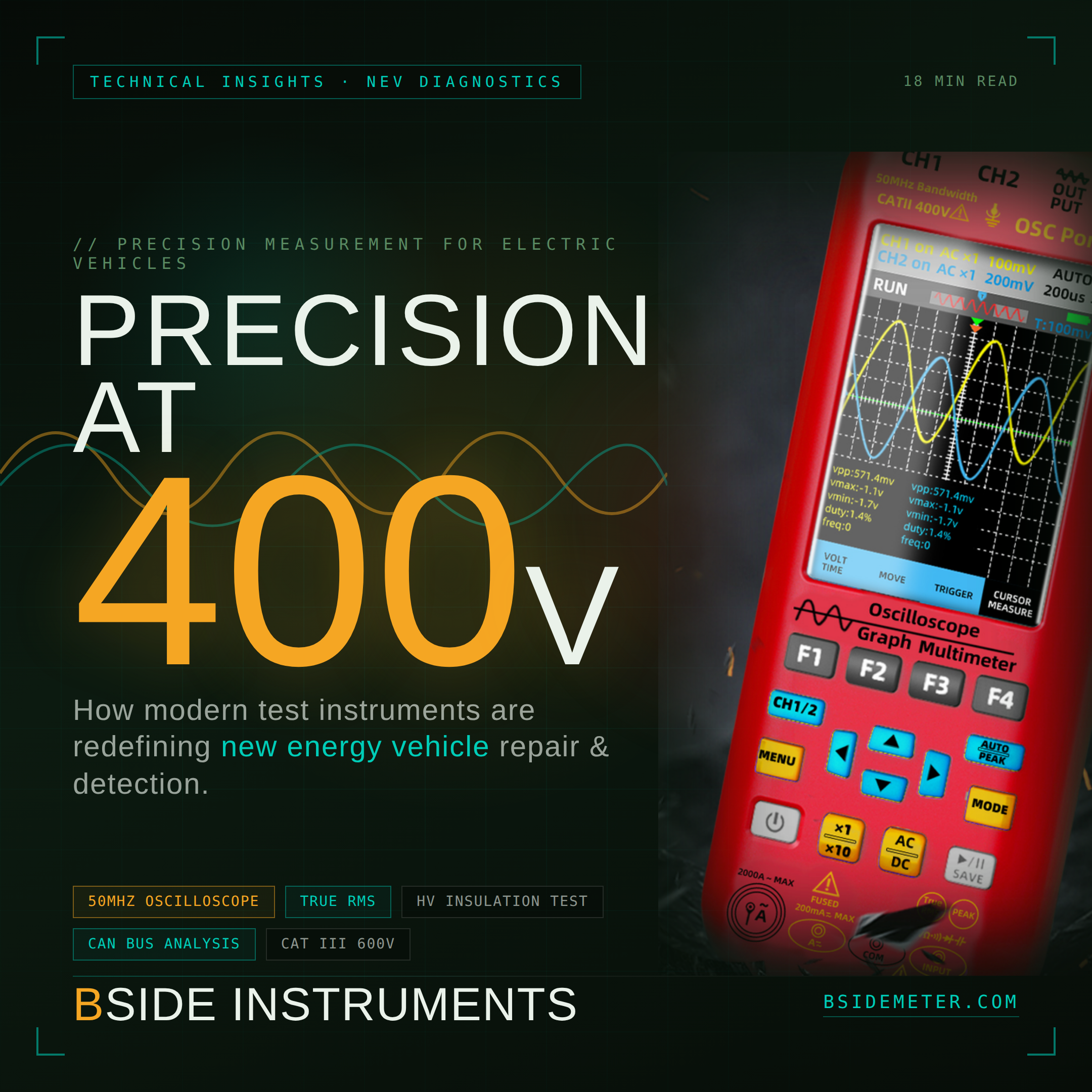
The O9 positions itself as a 4-in-1 handheld combining oscilloscope, multimeter, signal generator, and data recorder functions. In the context of NEV workshop use, the specifications that matter most are:
50 MHz dual-channel oscilloscope bandwidth — This is the figure that determines what signals the instrument can capture faithfully. CAN bus at 500 kbps has frequency content well below 1 MHz, so bandwidth is not the limiting factor there. The critical application is inverter switching waveform analysis: SiC MOSFET devices in modern EV inverters switch at edge rates that have significant harmonic content up to tens of megahertz. At 50 MHz bandwidth, the O9 can capture the overall shape of switching transitions and observe gross anomalies like excessive ringing or asymmetric edges — which covers the majority of field diagnostic needs — while being upfront about not offering the 200-500 MHz bandwidth of a lab-grade instrument used for device characterization.
True RMS measurement — This specification is non-negotiable for any NEV instrumentation. Regenerative braking superimposes AC ripple on DC bus voltages. PWM waveforms have RMS values that diverge significantly from their average values. A multimeter that computes its AC readings based on sine-wave assumptions (average-responding, RMS-calibrated) will give systematically incorrect readings in these waveform environments. True RMS computation measures the actual heating value of the signal regardless of waveshape.
±1000V voltage range and 2000A flexible coil clamp compatibility — High-voltage DC measurement to 1000V is necessary to directly probe HV bus points with appropriate isolation. The 2000A current measurement capability addresses traction motor phase currents during high-power drive events, as well as charging system current during DC fast-charge sessions.
CAT II 400V / CAT III 600V safety ratings — These ratings are determined by IEC 61010-1 and define the transient overvoltage immunity of the instrument's measurement inputs. CAT III applies to distribution-level fixed installations; CAT II applies to equipment connected to a low-voltage installation. For NEV high-voltage system access points that are internal to the vehicle, CAT III rating provides the appropriate protection margin against voltage spikes induced by switching events in adjacent inverter circuitry.
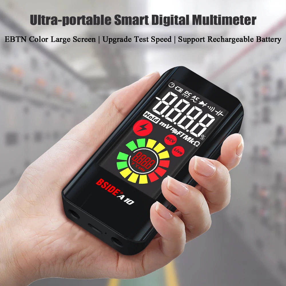
3.98-inch TFT color display with 480×320 resolution — This is less about specification numbers and more about usability under field conditions. A technician diagnosing a CAN bus fault with the hood up and engine bay lighting variable needs to read the waveform at a glance. Color channel differentiation between CH1 and CH2 waveforms, combined with a display large enough to show several waveform cycles simultaneously, reduces diagnostic time materially.
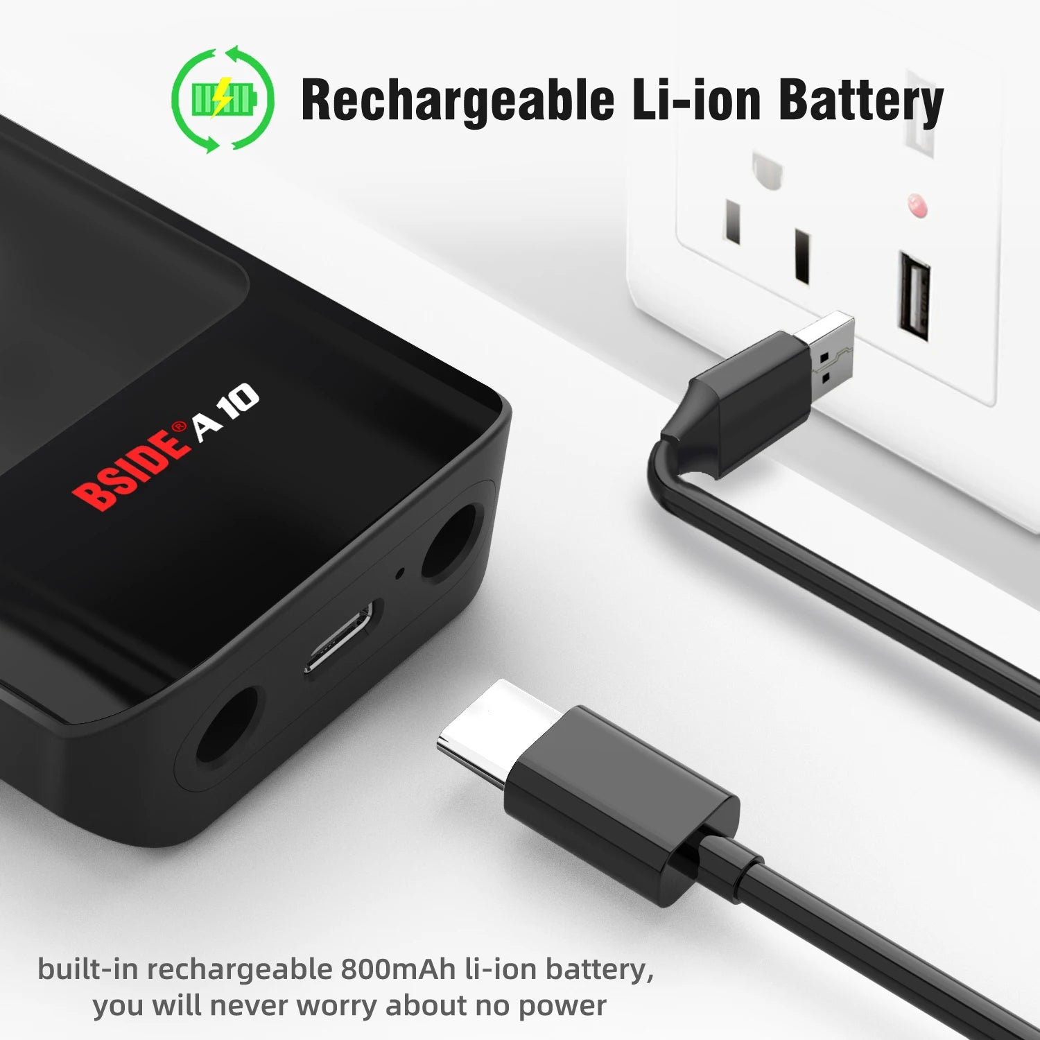
5000mAh rechargeable battery with USB-C charging — In a workshop context, instruments with disposable batteries are a recurring source of frustration: batteries die mid-diagnosis, require purchasing proprietary formats, and contribute to unnecessary waste. A 5000mAh lithium cell providing approximately ten hours of oscilloscope operation and twenty hours in multimeter mode means a full shift on a single charge, with standard USB-C recharging at any convenient point. This is the kind of detail that distinguishes instruments designed for actual field use from those optimized for laboratory bench work.
5.2 Clamp Meters in NEV High-Current Applications
Where the O9 addresses combined oscilloscope-multimeter functionality, BSIDE's clamp meter lineup addresses a different but equally important NEV diagnostic need: non-contact current measurement in high-current AC and DC circuits.
Traditional clamp meters using Hall-effect sensing are capable of DC current measurement, but many earlier models imposed response bandwidth limitations that made them unsuitable for capturing the dynamic current waveforms in an EV drivetrain. A traction motor phase current during a full-torque acceleration event is not a stable DC value — it is a sinusoidal AC current synthesized at the motor's electrical frequency, which may range from a few hertz at low speed to several hundred hertz at high speed. Measuring this with an instrument that struggles to track rapid changes produces readings that may be numerically plausible but dynamically misleading.
BSIDE clamp meters supporting True RMS measurement with adequate bandwidth address this requirement. When paired with the oscilloscope capability of the O9, a technician can observe the current waveform directly, checking for phase imbalance, harmonic distortion, or anomalous current spikes that might indicate a failing power stage in the inverter.
It is worth noting the safety implications of current measurement in NEV work. High-voltage AC cables connecting the inverter to the traction motor carry both high voltage to ground and high current. Opening these cables to insert a series-connected ammeter is not an option — it is dangerous, time-consuming, and often physically impossible without disassembling the drivetrain. The clamp meter's non-contact measurement principle, where the jaw simply surrounds the cable without requiring any circuit interruption, is the only practically workable approach, and it needs to maintain appropriate insulation ratings for the voltages present on the cable being measured.
5.3 Standard Multimeters in NEV Pre-Maintenance Protocols
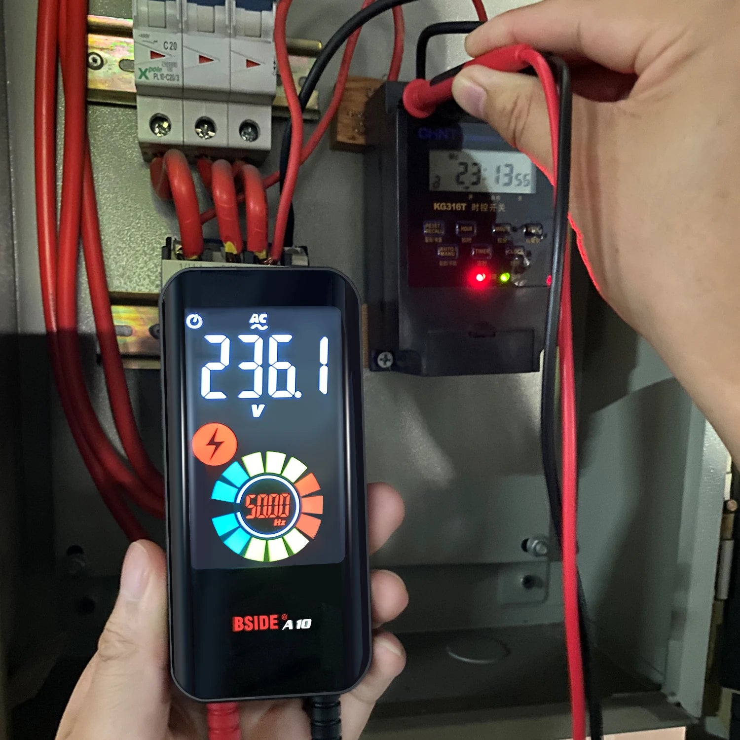
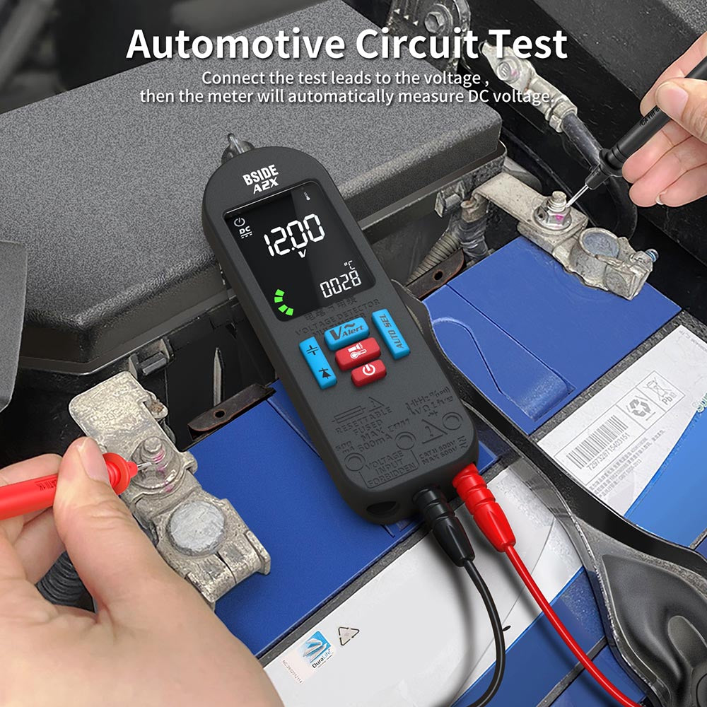
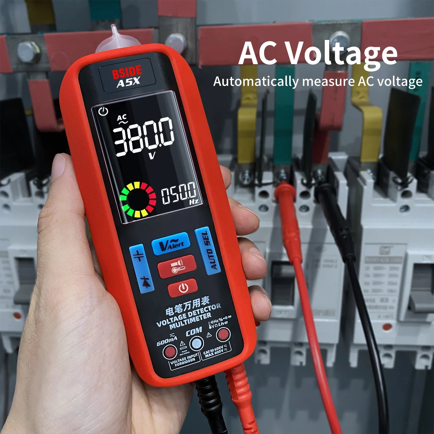
Before any technician begins physical work on an NEV's high-voltage systems, a standard pre-work protocol requires confirming that the HV system has been safely de-energized and that residual voltages have discharged to safe levels. This involves a sequence of measurements that any professional-grade multimeter with appropriate voltage range and CAT III rating can perform.
The procedure typically involves confirming that the HV isolation switch or service disconnect has been opened, waiting a prescribed discharge period for HV capacitors to discharge through bleed resistors, and then confirming with a direct measurement across the HV bus terminals that voltage has dropped to a safe level (typically below 60V DC, the threshold below which shock is generally considered non-hazardous). This is a measurement task, not a waveform analysis task, and it is one where the clarity and reliability of the instrument matter more than its oscilloscope capability.
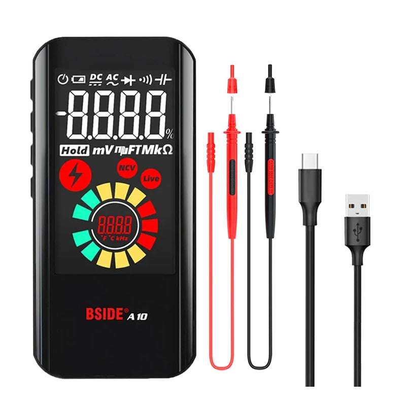
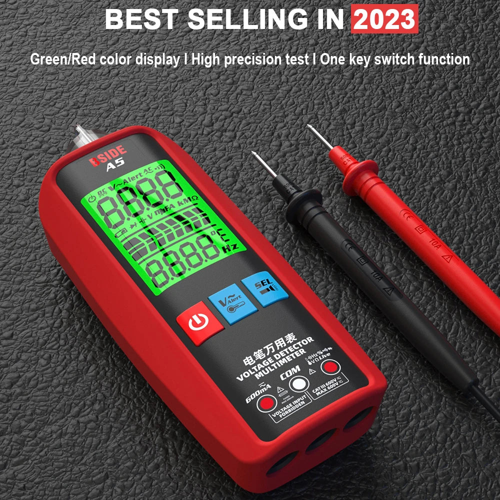
BSIDE's ZT and S-series multimeters, with their auto-ranging intelligence and EBTN backlit displays, are designed for exactly this kind of systematic measurement workflow. Auto-range mode means the technician does not need to dial in the correct range before probing — the instrument selects the appropriate input range automatically, reducing the risk of range-related damage to the measurement input and minimizing the procedural steps required before the reading appears on the screen.
6. The Insulation Resistance Testing Requirement
Of all the measurement tasks specific to NEV maintenance, insulation resistance testing deserves special attention because it is simultaneously the most safety-critical measurement and the one that most directly maps to the floating HV architecture described in Section 2.
The principle is straightforward: apply a known test voltage between the HV network (both positive and negative rails, tested separately) and the vehicle chassis, and measure the resulting resistance. Under regulations including China's GB 18384-2020 and the European ECE-R100, the minimum insulation resistance is specified at 100 Ω per volt of nominal battery voltage. For a 400V battery system, this means a minimum acceptable insulation resistance of 40 kΩ — a value that sounds substantial but represents a degradation of many orders of magnitude from the hundreds of megaohms present in a healthy system.
The test voltage applied during insulation measurement must exceed the battery's nominal voltage to stress-test the insulation properly. For a 400V pack, a test voltage of 500V is typical. This requirement immediately rules out any insulation resistance measurement using a standard multimeter's resistance function — the milliamp test current from a standard ohmmeter is not sufficient to properly characterize the dielectric properties of high-voltage cable insulation.
BSIDE's dedicated insulation measurement capability — available on selected instruments in the product line — applies the correct test voltage levels and measures insulation resistance in the megaohm range, providing the quantitative basis for an informed assessment of HV system integrity. This is not a measurement that should be estimated or approximated; it is a pass/fail criterion with direct implications for whether a vehicle is safe to return to service, and instrumentation calibrated to the task is what the situation demands.
The practical workflow for insulation testing typically involves:
- Confirming safe de-energization per the pre-work protocol
- Testing between HV+ bus and chassis, recording the resistance value and comparing against the manufacturer's specification
- Testing between HV– bus and chassis, recording and comparing
- Testing each high-voltage component (inverter, on-board charger, compressor, DC-DC converter) individually where the diagnosis requires component-level isolation
A value that passes the minimum threshold but is significantly lower than the baseline for that vehicle type can indicate developing degradation — perhaps water ingress beginning to track along a cable route — before it has progressed to the point of triggering the vehicle's own IMD fault code. This kind of trend-based interpretation is something a technician develops with experience, but it begins with having reliable numerical data from a properly calibrated instrument.
7. Practical Scenarios: Instrument Application in Realistic Fault Cases
It is one thing to describe measurement specifications abstractly. It is more useful to trace through how these instruments actually function during representative diagnostic scenarios.
Scenario A: Intermittent Charging Fault
A vehicle presents with an intermittent failure to initiate charging at a Level 2 AC charging station. The OBD system shows no stored fault codes, or shows only a vague "charging system communication fault" that clears after cycling the ignition.
The first step with an oscilloscope-equipped instrument is to observe the Control Pilot signal on the J1772 connector. This PWM signal communicates between the EVSE and the vehicle's on-board charger. The duty cycle encodes the available current capacity of the station. The vehicle responds by closing a relay to indicate it is ready to accept charge. In a correctly functioning system, this handshake happens within a defined time window, the CP signal transitions correctly, and charging begins.
When this process fails intermittently, the oscilloscope makes the failure mode visible in ways the OBD system cannot. Is the CP signal present but malformed? Is there a noise spike on the line that the vehicle's charger controller interprets as a protocol violation? Is the signal amplitude within specification? These are questions that an oscilloscope with a ten-second memory buffer — capturing and holding the waveform from the moment the cable is connected — can answer directly.
Scenario B: Motor Vibration at Specific Road Speeds
A vehicle exhibits a mechanical-feeling vibration at highway speeds that the driver reports as having appeared gradually over the past few months. Mechanical inspection finds no wheel or tire anomalies. Battery state of health is normal via OBD.
The diagnostic approach here involves probing the motor phase currents during a road test (or a loaded roller dynamometer test). With a True RMS clamp meter logging the phase current, and the oscilloscope capturing the current waveform in real time, a technician can observe whether the current in all three phases is balanced and sinusoidal. An inverter with a degrading gate drive circuit for one phase may produce a slight duty cycle imbalance that creates a torque ripple — a small periodic variation in motor output torque that manifests as vibration at a frequency related to the motor's pole count and electrical frequency.
This is a fault that would likely not produce an OBD code in its early stages. The inverter's self-diagnostics are designed to catch hard failures, not the subtle thermal drift of a gate resistor. But the waveform tells the story. Phase B current slightly lower than A and C, with a periodic envelope that explains exactly the resonance frequency the driver is experiencing.
Scenario C: High-Voltage Warning After Minor Collision
A vehicle comes into the workshop displaying a high-voltage system warning following a minor rear-end collision. Physical inspection shows no visible damage to accessible HV cabling, but the fault persists after clearing.
This is precisely the scenario that insulation resistance measurement is designed for. Even with no visible cable damage, an impact can damage the insulation of HV cables running through structural members, or compromise the seal on a connector, allowing moisture to enter. The IMD may have detected a momentary reduction in insulation resistance during the impact event and stored a fault.
Testing each HV component individually with an insulation tester identifies which part of the circuit has been compromised. Finding, for example, that the cable run between the battery pack and the inverter shows 800 kΩ rather than the hundreds of megaohms expected of intact insulation narrows the repair to a specific section of the HV harness without requiring full disassembly. The measurement saves hours of diagnostic time and provides documented evidence for the insurance assessment.
8. Safety as an Instrumentation Property
A point that sometimes gets overlooked in instrument selection discussions is that safety is not just a procedural property — it is a property of the instruments themselves. This matters in a few specific ways for NEV diagnostics.
Input protection against transient overvoltage is defined by the CAT rating system. When an inverter switches — even in a healthy system — it generates voltage transients that can appear on measurement probes connected to adjacent circuit nodes. A CAT III-rated instrument has been tested to withstand specified transient impulses without failure. An instrument without this rating may function correctly under normal conditions but fail during the kind of transient event that is common in a switching converter environment. In the worst case, this failure mode is not a blown fuse — it is a breakdown of the isolation between the input circuitry and the instrument's output, creating a shock hazard for the operator.
Insulated probe and lead construction matters independently of the instrument rating. Probes connecting to HV circuit points need their own insulation rating, and those ratings should be verified rather than assumed. Mismatched probes on a correctly rated instrument create a false sense of safety.
Double-insulated housing for handheld instruments used near HV systems means that a mechanical failure of the instrument casing does not create an exposure path to energized internal circuitry.
These are specifications that BSIDE publishes and that should be verified for any instrument used in NEV diagnostic work. The field is still young enough that there are instruments in commercial circulation with specifications that are technically correct but not appropriate for the environments where they are being used. Instrument selection is part of workshop safety planning, not separate from it.
9. The Democratization of Advanced Measurement
There is a broader story here that goes beyond any particular instrument specification. The history of oscilloscope technology in automotive workshops is largely a history of cost and complexity barriers that kept capable measurement out of the hands of most independent technicians.
A decade ago, a 50 MHz dual-channel digital oscilloscope suitable for automotive signal work would cost several thousand dollars, require a stable bench setup, and demand substantial training before a technician could use it productively. It was equipment for dealer-level service departments and large independent shops with dedicated diagnostic technicians, not for the small or medium workshop that handles the majority of aftermarket service work.
The integration of oscilloscope capability into handheld form factors at price points well below a thousand dollars — including the BSIDE O-series — represents a genuine shift in the accessibility of this measurement capability. A technician who can afford a good multimeter can now afford the oscilloscope capability to go with it, in the same package. The form factor means it works in the shop and on the vehicle, not just on a bench. The rechargeable battery means no mains power connection is needed.
This matters not just economically but diagnostically. Wider availability of capable instrumentation means more technicians encounter waveform-based diagnostic thinking in their daily work, develop the interpretation skills that come with experience, and are equipped to handle the signal environments that NEVs create. The skills gap around EV diagnostics is partly a training gap and partly an instrumentation gap. Closing the latter helps close the former.
10. Looking Forward: Where NEV Diagnostics Is Heading
A few developments on the horizon are worth noting for technicians and equipment purchasers thinking about what they will need in two to five years.
800-volt architectures are becoming increasingly common in premium EV platforms, driven by the faster charging rates that higher voltages enable. The Porsche Taycan, Hyundai Ioniq 6, Kia EV6, and newer platforms from multiple manufacturers operate at nominal voltages around 800V rather than 400V. This pushes insulation test voltage requirements higher and raises the bar on measurement input ratings. Instruments with 1000V input ratings are already appropriate for 800V systems with appropriate safety margin.
Silicon carbide (SiC) inverters are replacing older IGBT-based inverters at the high end of the market and increasingly in mainstream applications. SiC devices switch faster — edge rates of 100 nanoseconds or less are common — and this creates higher-frequency content in the switching waveform. Bandwidth requirements for inverter switching analysis move upward. For comprehensive field service of SiC-equipped vehicles, oscilloscope bandwidth above 100 MHz becomes relevant for capturing switching transient details.
Software-Defined Vehicle architectures are increasing the proportion of vehicle function implemented in software and communicated over increasingly capable in-vehicle networks. CAN FD (with up to 8 Mbps data phase) and Ethernet-based automotive networks (100BASE-T1, 1000BASE-T1) are appearing on new platforms. Oscilloscope-based protocol decoding for these higher-speed buses requires both adequate bandwidth and appropriate trigger/decode software support.
Battery second-life and repurposing as a growing area of aftermarket activity creates new measurement scenarios. Evaluating used battery modules for repurposing as stationary storage requires comprehensive cell-level voltage and capacity characterization — a measurement task that reaches beyond standard vehicle diagnostics.
BSIDE's product development roadmap reflects awareness of these trends. The specifications that make the current O-series appropriate for today's mainstream NEV work are being extended to accommodate the technical direction of the market.
11. Conclusion: Matching Instrument Capability to Technical Reality
The argument of this article, stated plainly, is this: new energy vehicle maintenance demands a different and more capable set of measurements than conventional automotive service. The signals that matter — PWM inverter waveforms, CAN bus communications, insulation resistance, True RMS high-voltage measurements, high-current DC motor drive — are not well served by instruments optimized for ICE diagnostics. The technician who approaches an EV with a conventional multimeter and a code reader will solve some problems and miss others.
The right instrumentation for this environment combines:
- True RMS voltage and current measurement with adequate voltage range for HV system work
- Two-channel oscilloscope capability with sufficient bandwidth to capture inverter and communication signals
- Insulation resistance measurement at appropriate test voltage levels
- CAT III safety ratings and fully insulated probe systems
- Portable, battery-powered form factors that function in the workshop environment
- Integrated signal generation capability for actuator and circuit testing
This is precisely the capability envelope that BSIDE's O-series oscilloscope graph multimeters and supporting clamp meter lineup are designed to occupy. Not at the price point of a professional-grade bench instrument, but at a price point that makes this capability accessible to the workshops that will service the majority of the world's growing EV fleet.
The vehicles are already on the road. The technicians are already in the workshops. The measurement capability to bridge between the two — that is the gap that purpose-designed instrumentation addresses.
About BSIDE
BSIDE (bsidemeter.com) designs and manufactures professional electronic test and measurement instruments for engineers, electricians, and automotive technicians. Our product line spans digital multimeters, oscilloscope graph multimeters, clamp meters, voltage testers, and insulation test instruments. All products are designed to deliver professional-grade measurement accuracy in portable, field-ready form factors.
Technical specifications referenced in this article are as published for the BSIDE O9 and associated product line. For the most current specification data, please refer to bsidemeter.com. Safety ratings compliance is verified per IEC 61010-1 standards.